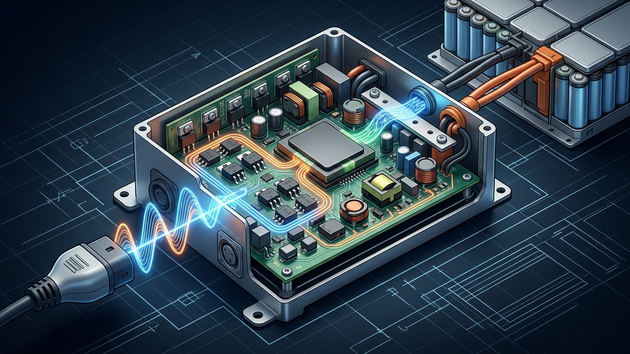
Every 19.2 kW single-phase charging session forces your car to soak up and give back about 51 joules, 120 times a second. Today a can of electrolytic capacitors does that job. A new single-stage onboard charger wants to delete the can. The physics says the energy still has to go somewhere.
At electronica in Munich on November 11, 2026, Visteon-Shinry Power Electronics (VSPE), the Visteon and SHINRY joint venture, announced it is working with Infineon on a single-stage onboard charger (OBC) built on Infineon's GaN monolithic bidirectional switches (BDS). The design merges the stages of a conventional two-stage OBC, eliminates the bulk capacitors, and supports 22 kW three-phase and 19.2 kW single-phase AC charging with full V2X (Visteon press release). The topology and control details are proprietary. The math below shows what any design like this must solve.
1. Two-Stage vs. Single-Stage OBC Architecture
A conventional OBC is two converters in series. A PFC stage turns grid AC into a fixed DC link of roughly 400 to 800 V, a bank of bulk capacitors holds that link steady, and an isolated DC/DC stage (often CLLC or dual active bridge) converts it to battery voltage. A single-stage OBC removes the DC link. It switches the AC line straight into a high-frequency transformer using a matrix-type or cycloconverter topology, so each switch must block voltage of both polarities.
Single-stage: AC → bidirectional switches → HF transformer → battery
Rating check (from the announcement):
22 kW 3-phase ≈ √3 × 400 V × 32 A = 22.2 kW
19.2 kW 1-phase = 240 V × 80 A (North American Level 2 maximum)
Efficiency also compounds. Two stages at 98.5% each give 0.985 × 0.985 ≈ 97.0% overall. One stage at 98% beats that. Those stage efficiencies are illustrative, not VSPE figures.
2. Single-Phase Ripple Power: Why the Bulk Capacitor Exists
On a single phase at unity power factor, instantaneous power is not constant. It pulses at twice the line frequency:
Energy swing per half-cycle: ΔE = P / ω
P = 19.2 kW, f = 60 Hz → ω = 377 rad/s
ΔE = 19,200 / 377 ≈ 51 J
Bulk cap needed: C = P / (ω · V_dc · ΔV)
V_dc = 450 V, ΔV = 45 V (10% p-p)
C = 19,200 / (377 × 450 × 45) ≈ 2.5 mF
That is 2.5 mF of 450 V-plus capacitance, typically electrolytic, which is bulky and one of the main wear-out parts in power electronics. Its job is to absorb the 120 Hz energy swing so the battery sees smooth DC. Delete the capacitor and that 51 J has to be handled somewhere else. The 450 V link and 10% ripple are our example design values.
3. Where the Ripple Goes: Battery Current RMS Math
If a single-stage OBC passes the power pulse straight through, the battery current carries it. With battery voltage roughly constant:
I_rms = I_avg · √(1 + ½) ≈ 1.22 · I_avg
19.2 kW into a 400 V pack:
I_avg = 48 A, I_peak = 96 A, I_rms ≈ 59 A
I²R loss vs. pure DC: (1.22)² ≈ 1.5×
So a "pure pass-through" design heats cables, connectors and cell resistance about 50% more than smooth DC at the same average power. Designers have three main options: accept the 120 Hz ripple in the battery, add a small active power decoupling circuit that stores the swing on a capacitor allowed to swing over a wide voltage range (energy scales with V², so a much smaller capacitor works), or shape the current with control. Which one VSPE uses is not disclosed. How much low-frequency ripple lithium-ion cells tolerate without extra ageing is still argued in the literature, so treat it as a design trade, not a settled number.
4. GaN Bidirectional Switch: The Die-Area and Conduction-Loss Formula
Matrix and cycloconverter topologies are old ideas. They stayed niche because each bidirectional switch used to be two MOSFETs back to back. Infineon's CoolGaN BDS 650 V G5 is a monolithic common-drain device with two independent gates that shares one drift region for blocking in both directions (Infineon product page).
Same R_total with two dies → each R/2 → each 2× area
Total silicon: 2 × 2A = 4A vs. ≈ A for a shared-drift BDS
Example at 32 A rms (22 kW phase current), worst case:
B2B 2 × 55 mΩ = 110 mΩ → 32² × 0.110 ≈ 113 W
BDS 55 mΩ → 32² × 0.055 ≈ 56 W
Infineon puts the area and cost advantage over back-to-back vertical MOSFETs at "almost a factor of 4" (Infineon application note), and a 55 mΩ BDS part, IGLT65R055B2, exists. The loss numbers assume one path carries full current continuously, so they are an upper-bound example. GaN's low switching loss also lets frequency rise, and transformer core size follows the area-product rule A_p = P / (K · B_max · J · f): double f, roughly halve A_p. Infineon's own 3.7 kW single-phase, single-stage OBC demo measures 162 × 108 × 29 mm, about 0.51 L, which is the >7 kW/L it claims at >97% full-load efficiency (Infineon CES 2026 demo).
- How VSPE handles 120 Hz ripple in 19.2 kW single-phase mode (battery ripple, active decoupling, or control). Not disclosed.
- VSPE's efficiency, power density, switching frequency and production timing. The announcement gives none.
- Whether the production design uses the 55 mΩ BDS or a different automotive part; our loss example assumes 55 mΩ.
- The ageing impact of 120 Hz ripple current on specific lithium-ion cells; published results differ.
The Engineering Takeaway on Single-Stage OBCs
- The capacitor exists for single-phase ripple. At 19.2 kW and 60 Hz, that is about 51 J per half-cycle, or roughly 2.5 mF at 450 V with 10% ripple.
- Three-phase is ripple-free. A 22 kW three-phase single-stage OBC can skip the bulk capacitor with no penalty from instantaneous power.
- Single-phase ripple has to go somewhere. Passing it through raises battery I²R loss by about 1.5×.
- Monolithic GaN BDS fixes the cost problem. Sharing one drift region cuts die area close to 4× compared with back-to-back switches.
For the other way to shrink charging hardware, reusing the traction inverter, see Integrated Charger-Inverter Explained. Remember that the OBC only matters for AC charging; DC fast charging bypasses it, and we tested how far real sessions fall below the sticker rating in 350 kW EV Charger, But Only 157 kW? on our YouTube channel.
Sources: Visteon press release (Nov 11, 2026); Infineon CoolGaN BDS product page; Infineon cycloconverter application note; Infineon CES 2026 3.7 kW OBC demo. Calculations by The Engineering Core using the illustrative assumptions stated above.


