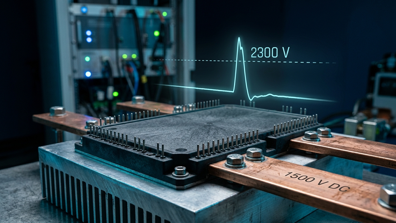
A 1500 V DC bus running on 1700 V transistors leaves you about 200 V of headroom. One fast switching edge can eat all of it.
That is the quiet problem behind solar inverters, grid batteries and megawatt chargers, and it is why Navitas' new 2300 V, 8 mΩ full-bridge SiC module (part family G4H08MT23GB4, in the standard SiCPAK footprint) matters more than the spec line suggests. Navitas announced it on October 21, 2026, aiming it at solid-state transformers (SST), grid-scale BESS, solar inverters and EV megawatt charging, and trade press picked it up in early November (Charged EVs, The Data Center Engineer).
Here is the engineering math that explains why the industry keeps pushing past 1700 V, and what a 2300 V rating actually buys on a 1500 V DC system.
1. 2300 V SiC headroom: the derating formula on a 1500 V DC bus
Device voltage is never sized to the nominal bus. Designers check the utilization ratio:
1700 V device on 1500 V bus: 1500 / 1700 = 88%
2300 V device on 1500 V bus: 1500 / 2300 = 65%
88% is uncomfortable for two reasons. First, the switching overshoot (point 2) stacks on top of the bus. Second, high-voltage power semiconductors suffer random failures from cosmic-ray neutrons, and that failure rate climbs steeply as the steady DC voltage approaches the rating. That is why long-life grid gear is commonly designed to run in roughly the 60–70% range of rated voltage (to verify: the exact derating target depends on each vendor's cosmic-ray FIT curves, which Navitas has not published for this part). A 2300 V part lands a 1500 V bus right inside that zone.
2. The overshoot math: why 1700 V runs out of room
Every turn-off pushes current through stray loop inductance, and the voltage spike follows a simple formula:
Example: 20 nH × 15 A/ns = 300 V
1500 V + 300 V = 1800 V > 1700 V rating
1500 V + 300 V = 1800 V = 78% of 2300 V
The 20 nH and 15 A/ns figures are illustrative example values, not Navitas data. The point holds anyway: with a 1700 V device you must slow the switching edge (bigger gate resistor, more switching loss) or fight for every nanohenry of layout. With 2300 V you can let SiC switch fast, which is the reason you paid for SiC in the first place.
3. Two-level vs three-level: the device-count comparison
Today most 1500 V inverters use three-level topologies (NPC or ANPC) built from 1200 V devices, because no single affordable switch could block the full bus with margin. A 2300 V switch makes a plain two-level bridge possible again.
3-level NPC (1200 V parts): 4 switches + 2 clamp diodes, 2 devices in the current path
2-level (2300 V parts): 2 switches, 1 device in the current path
Conduction loss per leg ≈ nseries × Irms2 × RDS(on)
Example at 200 A rms, 8 mΩ: 1 × 2002 × 0.008 = 320 W
The 200 A figure is an example operating point, not the module's rating, and RDS(on) rises with junction temperature, so the hot loss will be higher (to verify against the datasheet's temperature curve). The trade is real, not free: a two-level output has bigger voltage steps, so the filter and EMI work get harder. What you gain is half the gate drivers, simpler control and no neutral-point balancing.
4. SST architecture: higher-voltage cells mean fewer stages per phase
Navitas pitches the module as a medium-voltage building block for SSTs that turn grid power into the high-voltage DC used inside AI racks. In a cascaded SST, each phase is a stack of cells whose DC links add up to the phase peak voltage:
13.8 kV grid: 13,800 × 1.414 / 1.732 ≈ 11.3 kV
Ncells ≥ Vphase,peak / Vcell
800 V cells (1200 V devices): 11.3 / 0.8 ≈ 15 cells
1500 V cells (2300 V devices): 11.3 / 1.5 ≈ 8 cells
Those are minimum counts before redundancy (N+1) and grid over-voltage margin, so real designs carry more. Still, roughly halving the cell count cuts gate drivers, isolated auxiliary supplies and high-frequency transformers per phase. That is the same stacking logic we worked through in Solid-State Transformer Math Explained, just with a bigger brick. Navitas also lists an AlN substrate with over 5 kV isolation and epoxy potting it says gives 10x the thermal conductivity of silicone gel, both of which matter when every cell floats kilovolts above ground.
What to take away
- Check utilization first: VDC/Vrated near 65% is a comfortable zone for long-life gear; near 90% is a warning sign.
- Add L × di/dt to the bus before trusting any voltage rating.
- 2300 V parts let 1500 V systems go back to simpler two-level bridges, trading device count for filter work.
- In SSTs, cell voltage sets stage count, and stage count sets cost and reliability.
Want the 800 V version of this story? Our video on 800 V SiC power electronics on The Engineering Core walks through why SiC took over EV inverters first. For the rack side of the chain, see GaN IBC Architecture Explained.
Sources: Navitas press release (Oct 21, 2026); Charged EVs (Nov 5, 2026); The Data Center Engineer (Nov 6, 2026).


